
How to Install 40G QSFP+ Transceiver Modules?
2017-07-05
This installation note provides the installation instructions for the 40-Gigabit Quad Small Form-Factor Pluggable Plus (QSFP+) transceiver modules. The modules are hot-swappable input/output (I/O) devices that connect the system's module port electrical circuitry with either a copper or a fiber-optic network.
The 40-Gigabit QSFP+ transceiver module is a hot-swappable, parallel fiber-optical module with four independent optical transmit and receive channels. These channels can terminate in another 40-Gigabit QSFP+ transceiver, or the channels can be broken out to four separate 10-Gigabit SFP+ transceivers. (See Figure1)
The QSFP+ transceiver module connects the electrical circuitry of the system with either a copper or an optical external network. (See Figure 2 for a view of the optical QSFP+ transceiver.) The transceiver is used primarily in short reach applications in switches, routers, and data center equipment where it provides higher density than SFP+ modules.
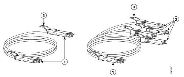
Figure 1 40-Gigabit QSFP+ Transceiver Module (Copper)
QSFP+ transceiver body
10GBASE SFP+ transceivers
Pull tab
Figure2 40-Gigabit QSFP+ Transceiver Module (Optical)
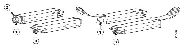
40GBASE QSFP+ transceiver body
Bail-clasp latch
Electrical connection to the module circuitry
Note: The multiple-fiber push-on (MPO) connectors and the duplex LC connectors on the optical QSFP+ transceivers support network interface cables with either Physical contact (PC) or Ultra-Physical Contact (UPC) flat-polished face types. The MPO connectors and the duplex LC connectors on the optical QSFP+ transceivers do not support network interface cables with an angle-polished contact (APC) face type.
The QSFP+ transceiver module can have either a bail-clasp latch or a pull-tab latch. Installation procedures for both types of latches are provided.
The QSFP+ transceiver module is a static-sensitive device. Always use an ESD wrist strap or similar individual grounding device when handling QSFP+ transceiver modules or coming into contact with system modules.
Before install the 40G QSFP+ transceiver module, you need these tools:
Wrist strap or other personal grounding device to prevent ESD occurrences.
Antistatic mat or antistatic foam to set the transceiver on.
Fiber-optic end-face cleaning tools and inspection equipment
To install an QSFP+ transceiver module, follow these steps:
Step 1 Attach an ESD wrist strap to yourself and a properly grounded point on the chassis or the rack.
Step 2 Remove the QSFP+ transceiver module from its protective packaging.
Step 3 Check the label on the QSFP+ transceiver module body to verify that you have the correct model for your network.
Step 4 For optical QSFP+ transceivers, remove the optical bore dust plug and set it aside.
Step 5 For transceivers equipped with a bail-clasp latch:
a. Keep the bail-clasp aligned in a vertical position.
b. Align the QSFP+ transceiver in front of the module's transceiver socket opening and carefully slide the QSFP+ transceiver into the socket until the transceiver makes contact with the socket electrical connector. (See Figure3.)
Step 6 For QSFP+ transceivers equipped with a pull-tab:
a. Hold the transceiver so that the identifier label is on the top.
b. Align the QSFP+ transceiver in front of the module's transceiver socket opening and carefully slide the QSFP+ transceiver into the socket until the transceiver makes contact with the socket electrical connector.
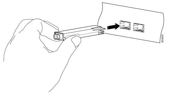
Figure 3 Installing the 40-Gigabit QSFP+ Transceiver Module (Optical Transceiver Equipped with a Bail-Clasp Latch Shown)
Step 7 Press firmly on the front of the QSFP+ transceiver with your thumb to fully seat the transceiver in the module's transceiver socket. (See Figure 4.) If the latch is not fully engaged, you might accidently disconnect the QSFP+ transceiver module.
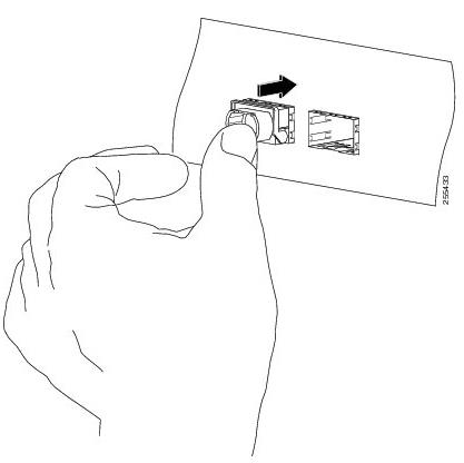
Figure 4 Seating the 40-Gigabit QSFP+ Transceiver Module (Optical Transceiver Equipped with a Bail-Clasp Latch Shown)
Step 8 For optical QSFP+ modules, reinstall the dust plug into the QSFP+ transceivers optical bore until you are ready to attach the network interface cable. Do not remove the dust plug until you are ready to attach the network interface cable.
SFP+ module,SFP+ transceiver,bidi sfp,XFP module,XFP transceiver Which is good? First choice Fiberland!Thanks for your concern, to learn more about Fiberland, please enter Fiberland website: http://www.fiberlandtec.com/
The 40-Gigabit QSFP+ transceiver module is a hot-swappable, parallel fiber-optical module with four independent optical transmit and receive channels. These channels can terminate in another 40-Gigabit QSFP+ transceiver, or the channels can be broken out to four separate 10-Gigabit SFP+ transceivers. (See Figure1)
The QSFP+ transceiver module connects the electrical circuitry of the system with either a copper or an optical external network. (See Figure 2 for a view of the optical QSFP+ transceiver.) The transceiver is used primarily in short reach applications in switches, routers, and data center equipment where it provides higher density than SFP+ modules.
Figure 1 40-Gigabit QSFP+ Transceiver Module (Copper)
QSFP+ transceiver body
10GBASE SFP+ transceivers
Pull tab
Figure2 40-Gigabit QSFP+ Transceiver Module (Optical)
40GBASE QSFP+ transceiver body
Bail-clasp latch
Electrical connection to the module circuitry
Note: The multiple-fiber push-on (MPO) connectors and the duplex LC connectors on the optical QSFP+ transceivers support network interface cables with either Physical contact (PC) or Ultra-Physical Contact (UPC) flat-polished face types. The MPO connectors and the duplex LC connectors on the optical QSFP+ transceivers do not support network interface cables with an angle-polished contact (APC) face type.
The QSFP+ transceiver module can have either a bail-clasp latch or a pull-tab latch. Installation procedures for both types of latches are provided.
The QSFP+ transceiver module is a static-sensitive device. Always use an ESD wrist strap or similar individual grounding device when handling QSFP+ transceiver modules or coming into contact with system modules.
Before install the 40G QSFP+ transceiver module, you need these tools:
Wrist strap or other personal grounding device to prevent ESD occurrences.
Antistatic mat or antistatic foam to set the transceiver on.
Fiber-optic end-face cleaning tools and inspection equipment
To install an QSFP+ transceiver module, follow these steps:
Step 1 Attach an ESD wrist strap to yourself and a properly grounded point on the chassis or the rack.
Step 2 Remove the QSFP+ transceiver module from its protective packaging.
Step 3 Check the label on the QSFP+ transceiver module body to verify that you have the correct model for your network.
Step 4 For optical QSFP+ transceivers, remove the optical bore dust plug and set it aside.
Step 5 For transceivers equipped with a bail-clasp latch:
a. Keep the bail-clasp aligned in a vertical position.
b. Align the QSFP+ transceiver in front of the module's transceiver socket opening and carefully slide the QSFP+ transceiver into the socket until the transceiver makes contact with the socket electrical connector. (See Figure3.)
Step 6 For QSFP+ transceivers equipped with a pull-tab:
a. Hold the transceiver so that the identifier label is on the top.
b. Align the QSFP+ transceiver in front of the module's transceiver socket opening and carefully slide the QSFP+ transceiver into the socket until the transceiver makes contact with the socket electrical connector.
Figure 3 Installing the 40-Gigabit QSFP+ Transceiver Module (Optical Transceiver Equipped with a Bail-Clasp Latch Shown)
Step 7 Press firmly on the front of the QSFP+ transceiver with your thumb to fully seat the transceiver in the module's transceiver socket. (See Figure 4.) If the latch is not fully engaged, you might accidently disconnect the QSFP+ transceiver module.
Figure 4 Seating the 40-Gigabit QSFP+ Transceiver Module (Optical Transceiver Equipped with a Bail-Clasp Latch Shown)
Step 8 For optical QSFP+ modules, reinstall the dust plug into the QSFP+ transceivers optical bore until you are ready to attach the network interface cable. Do not remove the dust plug until you are ready to attach the network interface cable.
SFP+ module,SFP+ transceiver,bidi sfp,XFP module,XFP transceiver Which is good? First choice Fiberland!Thanks for your concern, to learn more about Fiberland, please enter Fiberland website: http://www.fiberlandtec.com/
RECENT BLOG POST
-
012019-10With the continuous development of 5G communication technology, 100G modules are gradually becoming popular. We know that there are many kinds of packages for 100G optical modules. From 2000 to now, the optical module package types have been rapidly developed. Its main package types are: GBIC, SFP, XENPAK, SNAP12, X2, XFP, SFP+, QSFP/QSFP+, CFP, CXP. In the fast-developing network era, some 100G optical modules avoid the risk of being eliminated, and upgraded and revised with the wave of the Internet, such as 100G CFP optical modules.
-
012019-101. What is the CWDM SFP? The CWDM optical module is an optical module using CWDM technology to implement the connection between the existing network device and the CWDM multiplexer/demultiplexer. When used with a CWDM multiplexer/demultiplexer, CWDM optical modules can increase network capacity by transmitting multiple data channels with separate optical wavelengths (1270 nm to 1610 nm) on the same single fiber.
-
012019-10AOC is the abbreviation of Active Optical Cables, which is called Active Optical Cables in Chinese. AOC active optical is to encapsulate two optical modules and cable together. Because the medium of transmission in the middle is optical cable, AOC optical module, which contains laser devices, has a higher price for DAC. However, its optical aperture is not exposed, it has high reliability, and its working distance can be customized for a long distance of less than 100 meters.
-
012019-10Dense Wavelength Division Multiplexing (DWDM) technology is capable of transmitting data in an optical fiber using bit wavelength parallel transmission or string line transmission using the wavelength of the laser.It is widely used in different fields of communication networks, including long-distance backbone networks, metropolitan area networks (MANs), residential access networks, and local area networks (LANs).The DWDM optical module is the optical module that uses this technology, so the DWDM optical module has high bandwidth and long-distance transmission characteristics.


