Do you know the new generation of data center switching architecture?
2017-09-30
The current cloud computing service is developing rapidly, ultra-large-scale, ultra-high performance, flexible and highly scalable to become the characteristics and basic requirements of cloud computing business model, traditional technology-based switch and router switching architecture can not be applied to this large-scale, high density of it distribution mode, while the unified switching architecture and business integration, greater capacity and bandwidth , higher performance and scalability, more granular QoS assurance, higher reliability and fault-tolerant performance, intelligent and easy to manage, green energy saving technology direction of the new basic Network Exchange architecture, to meet the emerging new business and applications, improve user experience, and continue to reduce the cost of unit bandwidth. The progress of network technology architecture, in turn, further promotes the popularization and benign development of cloud computing. The cache swap is used for its line cards as a component of fully distributed business processing and forwarding.
The switching architecture is the core of the network equipment, as important as the human heart. The switching architecture determines the key attributes of a device’s capacity, performance, scalability, and QoS. In its short more than 20-year history, there are different forms such as shared bus exchange, shared storage Exchange, crossbar matrix Exchange, and Clos Exchange architecture based on dynamic routing. In the case of a large capacity or High-capacity rack network device representing the industry’s development level, a crossbar matrix switching or Clos switching architecture is usually used, and the shared cache Exchange is applied to its line card as a component of fully distributed business processing and forwarding.
Data center requirements for next-generation switching architectures
The general model of the switching architecture, as shown in Figure 1, is logically composed of the two complementary parts of the data channel resource and the control channel resource. The data channel resources specifically include the switching network and its port bandwidth, the switching Fabric adaptor adapter, the Traffic Manager (TM), the buffering, and the high-speed bus for interconnection. The control channel resource includes the flow control unit, the Scheduler for resource allocation, business scheduling, congestion management, and the schedule is sometimes called the arbiter. The complete Exchange architecture also includes a message Packet Processor (PP) or network processor (NP).
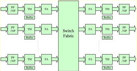
Figure 1 Exchange Architecture General model
The data center, as an application-oriented integrated service platform and the core infrastructure of cloud computing in the future, puts forward more comprehensive and demanding requirements for the switching architecture of network equipment, including support for unified switching architecture, large capacity and high scalability, forwarding Performance, business scheduling, and fine QoS, flexibility.
Support Unified Switch Fabric
The data center currently has three relatively independent networks: Data, Storage and SAN, and High-Performance Computing (HPC). In order to facilitate future business integration and service provision, simplify management, reduce construction costs and operation and maintenance costs, the triple play will gradually converge. The interface of the network device can easily expand and support interfaces such as FCoE and FC and its forwarding to integrate seamlessly with the storage network. It supports new interfaces such as CEE (Convergence Enhanced Ethernet) Enhanced Ethernet, “Best-effort” becomes a more mature “lossless”.
High Capacity & Scalability
The broadband era is coming, with Youtube, iTunes, Facebook, GoogleEarth, telepresence system, mobile video as the representative of the video stream, audio streaming, social networking, P2P, multimedia and other business is about 70% annual growth rate of development, Providing near-endless bandwidth requirements for future networks. Requires the switch with high capacity and excellent scalability, that is, with the business expansion and gradually expand the port number, port rate, thereby enhancing the port capacity. Extensibility also includes the ability to extend new port types based on business needs, support network resource virtualization, and support clustering systems.
As a key indicator of the ability to measure systems and future scalability, the exchange capacity of the switch is equivalent to the vehicle’s displacement index. A new generation of rack-mounted data center switch exchange capacity in the 1 ~ 10Tbps level, the cluster system up to dozens of Tbps. Port capacity refers to the maximum number of network ports that can be provided by the current version of the product, multiplied by the corresponding line-rate port number by the network port rate, characterizing the wire-speed forwarding capability that the product currently supports. The same capacity of the product, in different versions and stages, may have different port capacity; the same exchange capacity of the product, due to the total cost of the exchange architecture is different, can support the port capacity will be different.
Port rate: A new generation of architecture requirements in addition to supporting Gigabit, 10 Gigabit Ethernet ports, but also requires a smooth slot to support a number of 40Gbps and 100Gbps ports, which is a qualitative leap in the development of bandwidth.
Forwarding performance
Line-rate forwarding performance: usually refers to the 64-byte packet-line forwarding capability, characterizing the ability of the system to process packet headers. Under the same port traffic, the 64-byte packet requires the system to process more reports in unit time The number of words. The forward performance also pays attention to wire-speed consistency, that is, large packets can be wire-speed, not packet loss; Pair mode, Full Mesh mode can wire-speed forwarding.
Forward delay and delay jitter: the current storage and forwarding technology port to port delay in a few microseconds to tens of microseconds, to meet the vast majority of applications. Cut-through forwarding delay can be up to 1 microsecond, mainly for a small number of delay is very sensitive to tight coupling high-performance computing. Time-delay jitter refers to the consistency of delay, time-delay predictability, real-time business such as VoIP, video, etc., usually require low latency and delay coherence.
Business scheduling and fine QoS
In recent years, the demand for bandwidth has reached 50 to 70 percent annual growth, while bandwidth supply is growing at 30 percent per annum. Resources are always limited, it is impossible for all users, all businesses to provide sufficient bandwidth, resulting in the actual network is a congested network. Network equipment needs to provide better and fine QoS support, that is, according to different users of different business SLA requirements, to provide the corresponding guaranteed or predictable bandwidth, packet loss rate, burst cache capacity, delay, delay jitter and other indicators.
Scheduling & Queuing: There is no business scheduling of the exchange structure is like no traffic lights at the crossroads, prone to collision and accidents, not to mention QoS. Extensive dispatching like every direction has a lane, with a single circular traffic light at the crossroads, there is no significant improvement over the traffic lights but is easy to block. And the fine scheduling is like three lanes in each direction (turn left, straight, turn right), the traffic lights are made up of three corresponding directional arrows (turn left, straight, right turn arrow), this schedule is obviously more efficient, More orderly.
In the switch, the lane is like a queue, traffic lights like a scheduler. The more the queue, the traffic can be more refined management and scheduling, so that different exports, different priorities of the business forwarding does not affect each other to eliminate the first block. The more queues, the more complex the scheduler, the higher the complexity of the design and some devices also support hierarchical scheduling (H-QoS). Can support the number of queues is one of the key indicators of network equipment, the general equipment to support more than a dozen, dozens to hundreds of queues ranging from a few high-end products can support 1K, more than a dozen K or dozens of K.
Traffic Classification & Buffering): Flow classification and caching are closely related to the business schedule. Traffic classification is to identify different users and businesses and then map to different priorities and queues. Without Buffering or Buffering is too small, good scheduling is also nominal or large discount. As applications become more complex, traffic bursts become more and more frequent (such as search business), and large enough caching is critical to a new generation of data centers.
Resiliency of the switching architecture
Elasticity refers to the failure of components, or man-made errors, can be automatically detected, and the fault isolation, so that the system function performance is not lost or as little as a possible loss (Graceful Degradation). Including redundancy (redundancy) and fault tolerance (Fault Tolerance). The physical separation of the N + 1 switching network board, that is, the forwarding plane and the control plane is physically advantageous to further improve the flexibility of the system.
Traditional CIOQ-based Crossbar switching architecture
Crossbar switching architecture based on CIOQ appeared in the 1990s. As shown in Figure 2, the architecture consists of one or more concurrently working unstacked Crossbar chips. Each Crossbar chip is connected to all the input ports corresponding to the FA port and all output ports. FA ports; service scheduling is usually done using a centralized arbiter, connected to all input and output FA chips and Crossbar chips; export FA timing or real-time reporting to the arbitrator export congestion. A typical exchange process consists of three steps: (1) Before sending the port to send the service, the gateway FA sends the request to transmit to the arbiter; (2) The arbitrator sends to the ingress FA according to the congestion of the output port queue (Granted); (3) business through the switching network forwarded to the output port.
(1) Before sending the port to send the service, the gateway FA sends the request to transmit to the arbiter;
(2) The arbitrator sends to the ingress FA according to the congestion of the output port queue (Granted);
(3) business through the switching network forwarded to the output port.
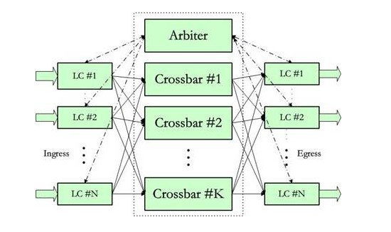
Figure 2 Crossbar Exchange architecture based on CIOQ
In the ingress direction, the cache uses VoQ (Virtual Output Queuing) to assign different queues to the different destination traffic ports, and allocate the corresponding queues to different traffic flows to buffer the ingress traffic. In the export direction, there is also a cache, used to absorb the exchange network over the sudden flow. So-called CIOQ (Combined Input Output Queuing).
Because it is centralized scheduling, so the arbiter scheduling algorithm is very complex, poor performance scalability, the system capacity is easy to form a bottleneck when the schedule, it is difficult to achieve accurate scheduling.
The crossbar based on CIOQ satisfies the requirement of large capacity exchange and better business scheduling, and is a comparatively perfect exchange architecture, the exchange capacity can be from hundreds of G to several T, and the 10G interface is usually supported but the 40G and 100G interfaces are not supported. Because the exchange capacity is not very large, the switching network is usually integrated on the main control board, using $number Master or load sharing work mode.
A New Generation of CLOS Switching Architecture Based on Dynamic Routing
The CLOS exchange architecture was first proposed by the Bell Labs, Dr. Charles Clos, in the 1953 “Non-blocking Exchange Network Study” paper, which was widely used in TDM networks. To commemorate this significant achievement, the CLOS named this Architecture. Nearly two decades of the packet-switched network of high-speed development, the urgent need for large capacity and excellent scalability of the exchange structure, CLOS this old and innovative technology once again full of exuberant vitality.
The CLOS switching architecture is a multi-level architecture; at each level, each switching unit is connected to all the switching units at the next level. A typical CLOS switching three-level architecture is defined by (k, n) two parameters, as shown in Figure 3, the parameter k is the number of intermediate-level switching units, n is the first level (third level) exchange unit Quantity. The first and third stages consist of n k × k switching units, and the intermediate stage consists of k n × n switching units. The entire network consists of k × n, that is, the network has k × n input and output ports.
For a higher capacity switching network, the intermediate level can also be a Class 3 CLOS network (that is, CLOS network can be recursively built), such as four first (three) n × n chip with two n × n The second chip can form a 2n × 2n switching network. Due to the recursive nature of the CLOS network, it has an unparalleled scalability, in theory, supporting the smooth expansion of the number of switch ports, port speed, and system capacity.
CLOS switching architecture can be strictly non-blocking, Re-arrangeable, Scalable.
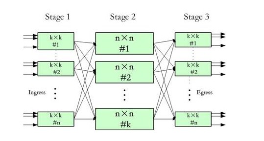
Figure 3 Clos Exchange architecture
The dynamic routing key point is that the load sharing can be balanced using all reachable paths. For the first level, each service flow can be sent uniformly to the k-level (usually cell-based) by round-robin or random mode; the traffic arrives at the second level will be based on the cell Cell-based self-routing, which switches the corresponding path to the third-level destination port according to the routing network. When the third level receives all the cells from the second level, the cells are reassembled into packets and the message order is correct. The dynamic routing approach thus implements a strictly non-blocking switch and helps to reduce the speed ratio to improve the effective port capacity.
Dynamic routing has a prominent advantage, that is, smooth support for higher rates of network ports, such as 40GE / 100GE. This is because it can take full advantage of all available paths to form a large data stream channel, such as 24 3.125Gbps channels that can support 100GE data streams. In contrast, static routing is limited by the bandwidth of a single path, such as Crossbar switching based on the XAUI interface. The maximum network port rate can only reach 10 Gbps and can not support 40GE and 100GE.
As the CLOS switching system capacity is very large, the physical implementation, usually using N + 1 independent switching network slot, and the control board control plane completely separated, on the one hand, to improve the system capacity scalability, on the other hand, a great degree To improve the reliability of the forwarding plane, to avoid the control plane failure or switching on the forwarding plane impact.
Conclusion
For high-end rack switches and routers, based on CIOQ crossbar switching architectures and Clos switching architectures. Among them, the Clos switching architecture based on dynamic routing and the signal-routing technology and distributed scheduling technology is the most advanced, perfect and ideal exchange architectures for the new generation of data center and cloud computing, which is applied to many business complex applications, such as large-capacity core switches and core routers.
The switching architecture is the core of the network equipment, as important as the human heart. The switching architecture determines the key attributes of a device’s capacity, performance, scalability, and QoS. In its short more than 20-year history, there are different forms such as shared bus exchange, shared storage Exchange, crossbar matrix Exchange, and Clos Exchange architecture based on dynamic routing. In the case of a large capacity or High-capacity rack network device representing the industry’s development level, a crossbar matrix switching or Clos switching architecture is usually used, and the shared cache Exchange is applied to its line card as a component of fully distributed business processing and forwarding.
Data center requirements for next-generation switching architectures
The general model of the switching architecture, as shown in Figure 1, is logically composed of the two complementary parts of the data channel resource and the control channel resource. The data channel resources specifically include the switching network and its port bandwidth, the switching Fabric adaptor adapter, the Traffic Manager (TM), the buffering, and the high-speed bus for interconnection. The control channel resource includes the flow control unit, the Scheduler for resource allocation, business scheduling, congestion management, and the schedule is sometimes called the arbiter. The complete Exchange architecture also includes a message Packet Processor (PP) or network processor (NP).
Figure 1 Exchange Architecture General model
The data center, as an application-oriented integrated service platform and the core infrastructure of cloud computing in the future, puts forward more comprehensive and demanding requirements for the switching architecture of network equipment, including support for unified switching architecture, large capacity and high scalability, forwarding Performance, business scheduling, and fine QoS, flexibility.
Support Unified Switch Fabric
The data center currently has three relatively independent networks: Data, Storage and SAN, and High-Performance Computing (HPC). In order to facilitate future business integration and service provision, simplify management, reduce construction costs and operation and maintenance costs, the triple play will gradually converge. The interface of the network device can easily expand and support interfaces such as FCoE and FC and its forwarding to integrate seamlessly with the storage network. It supports new interfaces such as CEE (Convergence Enhanced Ethernet) Enhanced Ethernet, “Best-effort” becomes a more mature “lossless”.
High Capacity & Scalability
The broadband era is coming, with Youtube, iTunes, Facebook, GoogleEarth, telepresence system, mobile video as the representative of the video stream, audio streaming, social networking, P2P, multimedia and other business is about 70% annual growth rate of development, Providing near-endless bandwidth requirements for future networks. Requires the switch with high capacity and excellent scalability, that is, with the business expansion and gradually expand the port number, port rate, thereby enhancing the port capacity. Extensibility also includes the ability to extend new port types based on business needs, support network resource virtualization, and support clustering systems.
As a key indicator of the ability to measure systems and future scalability, the exchange capacity of the switch is equivalent to the vehicle’s displacement index. A new generation of rack-mounted data center switch exchange capacity in the 1 ~ 10Tbps level, the cluster system up to dozens of Tbps. Port capacity refers to the maximum number of network ports that can be provided by the current version of the product, multiplied by the corresponding line-rate port number by the network port rate, characterizing the wire-speed forwarding capability that the product currently supports. The same capacity of the product, in different versions and stages, may have different port capacity; the same exchange capacity of the product, due to the total cost of the exchange architecture is different, can support the port capacity will be different.
Port rate: A new generation of architecture requirements in addition to supporting Gigabit, 10 Gigabit Ethernet ports, but also requires a smooth slot to support a number of 40Gbps and 100Gbps ports, which is a qualitative leap in the development of bandwidth.
Forwarding performance
Line-rate forwarding performance: usually refers to the 64-byte packet-line forwarding capability, characterizing the ability of the system to process packet headers. Under the same port traffic, the 64-byte packet requires the system to process more reports in unit time The number of words. The forward performance also pays attention to wire-speed consistency, that is, large packets can be wire-speed, not packet loss; Pair mode, Full Mesh mode can wire-speed forwarding.
Forward delay and delay jitter: the current storage and forwarding technology port to port delay in a few microseconds to tens of microseconds, to meet the vast majority of applications. Cut-through forwarding delay can be up to 1 microsecond, mainly for a small number of delay is very sensitive to tight coupling high-performance computing. Time-delay jitter refers to the consistency of delay, time-delay predictability, real-time business such as VoIP, video, etc., usually require low latency and delay coherence.
Business scheduling and fine QoS
In recent years, the demand for bandwidth has reached 50 to 70 percent annual growth, while bandwidth supply is growing at 30 percent per annum. Resources are always limited, it is impossible for all users, all businesses to provide sufficient bandwidth, resulting in the actual network is a congested network. Network equipment needs to provide better and fine QoS support, that is, according to different users of different business SLA requirements, to provide the corresponding guaranteed or predictable bandwidth, packet loss rate, burst cache capacity, delay, delay jitter and other indicators.
Scheduling & Queuing: There is no business scheduling of the exchange structure is like no traffic lights at the crossroads, prone to collision and accidents, not to mention QoS. Extensive dispatching like every direction has a lane, with a single circular traffic light at the crossroads, there is no significant improvement over the traffic lights but is easy to block. And the fine scheduling is like three lanes in each direction (turn left, straight, turn right), the traffic lights are made up of three corresponding directional arrows (turn left, straight, right turn arrow), this schedule is obviously more efficient, More orderly.
In the switch, the lane is like a queue, traffic lights like a scheduler. The more the queue, the traffic can be more refined management and scheduling, so that different exports, different priorities of the business forwarding does not affect each other to eliminate the first block. The more queues, the more complex the scheduler, the higher the complexity of the design and some devices also support hierarchical scheduling (H-QoS). Can support the number of queues is one of the key indicators of network equipment, the general equipment to support more than a dozen, dozens to hundreds of queues ranging from a few high-end products can support 1K, more than a dozen K or dozens of K.
Traffic Classification & Buffering): Flow classification and caching are closely related to the business schedule. Traffic classification is to identify different users and businesses and then map to different priorities and queues. Without Buffering or Buffering is too small, good scheduling is also nominal or large discount. As applications become more complex, traffic bursts become more and more frequent (such as search business), and large enough caching is critical to a new generation of data centers.
Resiliency of the switching architecture
Elasticity refers to the failure of components, or man-made errors, can be automatically detected, and the fault isolation, so that the system function performance is not lost or as little as a possible loss (Graceful Degradation). Including redundancy (redundancy) and fault tolerance (Fault Tolerance). The physical separation of the N + 1 switching network board, that is, the forwarding plane and the control plane is physically advantageous to further improve the flexibility of the system.
Traditional CIOQ-based Crossbar switching architecture
Crossbar switching architecture based on CIOQ appeared in the 1990s. As shown in Figure 2, the architecture consists of one or more concurrently working unstacked Crossbar chips. Each Crossbar chip is connected to all the input ports corresponding to the FA port and all output ports. FA ports; service scheduling is usually done using a centralized arbiter, connected to all input and output FA chips and Crossbar chips; export FA timing or real-time reporting to the arbitrator export congestion. A typical exchange process consists of three steps: (1) Before sending the port to send the service, the gateway FA sends the request to transmit to the arbiter; (2) The arbitrator sends to the ingress FA according to the congestion of the output port queue (Granted); (3) business through the switching network forwarded to the output port.
(1) Before sending the port to send the service, the gateway FA sends the request to transmit to the arbiter;
(2) The arbitrator sends to the ingress FA according to the congestion of the output port queue (Granted);
(3) business through the switching network forwarded to the output port.
Figure 2 Crossbar Exchange architecture based on CIOQ
In the ingress direction, the cache uses VoQ (Virtual Output Queuing) to assign different queues to the different destination traffic ports, and allocate the corresponding queues to different traffic flows to buffer the ingress traffic. In the export direction, there is also a cache, used to absorb the exchange network over the sudden flow. So-called CIOQ (Combined Input Output Queuing).
Because it is centralized scheduling, so the arbiter scheduling algorithm is very complex, poor performance scalability, the system capacity is easy to form a bottleneck when the schedule, it is difficult to achieve accurate scheduling.
The crossbar based on CIOQ satisfies the requirement of large capacity exchange and better business scheduling, and is a comparatively perfect exchange architecture, the exchange capacity can be from hundreds of G to several T, and the 10G interface is usually supported but the 40G and 100G interfaces are not supported. Because the exchange capacity is not very large, the switching network is usually integrated on the main control board, using $number Master or load sharing work mode.
A New Generation of CLOS Switching Architecture Based on Dynamic Routing
The CLOS exchange architecture was first proposed by the Bell Labs, Dr. Charles Clos, in the 1953 “Non-blocking Exchange Network Study” paper, which was widely used in TDM networks. To commemorate this significant achievement, the CLOS named this Architecture. Nearly two decades of the packet-switched network of high-speed development, the urgent need for large capacity and excellent scalability of the exchange structure, CLOS this old and innovative technology once again full of exuberant vitality.
The CLOS switching architecture is a multi-level architecture; at each level, each switching unit is connected to all the switching units at the next level. A typical CLOS switching three-level architecture is defined by (k, n) two parameters, as shown in Figure 3, the parameter k is the number of intermediate-level switching units, n is the first level (third level) exchange unit Quantity. The first and third stages consist of n k × k switching units, and the intermediate stage consists of k n × n switching units. The entire network consists of k × n, that is, the network has k × n input and output ports.
For a higher capacity switching network, the intermediate level can also be a Class 3 CLOS network (that is, CLOS network can be recursively built), such as four first (three) n × n chip with two n × n The second chip can form a 2n × 2n switching network. Due to the recursive nature of the CLOS network, it has an unparalleled scalability, in theory, supporting the smooth expansion of the number of switch ports, port speed, and system capacity.
CLOS switching architecture can be strictly non-blocking, Re-arrangeable, Scalable.
Figure 3 Clos Exchange architecture
The dynamic routing key point is that the load sharing can be balanced using all reachable paths. For the first level, each service flow can be sent uniformly to the k-level (usually cell-based) by round-robin or random mode; the traffic arrives at the second level will be based on the cell Cell-based self-routing, which switches the corresponding path to the third-level destination port according to the routing network. When the third level receives all the cells from the second level, the cells are reassembled into packets and the message order is correct. The dynamic routing approach thus implements a strictly non-blocking switch and helps to reduce the speed ratio to improve the effective port capacity.
Dynamic routing has a prominent advantage, that is, smooth support for higher rates of network ports, such as 40GE / 100GE. This is because it can take full advantage of all available paths to form a large data stream channel, such as 24 3.125Gbps channels that can support 100GE data streams. In contrast, static routing is limited by the bandwidth of a single path, such as Crossbar switching based on the XAUI interface. The maximum network port rate can only reach 10 Gbps and can not support 40GE and 100GE.
As the CLOS switching system capacity is very large, the physical implementation, usually using N + 1 independent switching network slot, and the control board control plane completely separated, on the one hand, to improve the system capacity scalability, on the other hand, a great degree To improve the reliability of the forwarding plane, to avoid the control plane failure or switching on the forwarding plane impact.
Conclusion
For high-end rack switches and routers, based on CIOQ crossbar switching architectures and Clos switching architectures. Among them, the Clos switching architecture based on dynamic routing and the signal-routing technology and distributed scheduling technology is the most advanced, perfect and ideal exchange architectures for the new generation of data center and cloud computing, which is applied to many business complex applications, such as large-capacity core switches and core routers.
RECENT BLOG POST
-
012019-10With the continuous development of 5G communication technology, 100G modules are gradually becoming popular. We know that there are many kinds of packages for 100G optical modules. From 2000 to now, the optical module package types have been rapidly developed. Its main package types are: GBIC, SFP, XENPAK, SNAP12, X2, XFP, SFP+, QSFP/QSFP+, CFP, CXP. In the fast-developing network era, some 100G optical modules avoid the risk of being eliminated, and upgraded and revised with the wave of the Internet, such as 100G CFP optical modules.
-
012019-101. What is the CWDM SFP? The CWDM optical module is an optical module using CWDM technology to implement the connection between the existing network device and the CWDM multiplexer/demultiplexer. When used with a CWDM multiplexer/demultiplexer, CWDM optical modules can increase network capacity by transmitting multiple data channels with separate optical wavelengths (1270 nm to 1610 nm) on the same single fiber.
-
012019-10AOC is the abbreviation of Active Optical Cables, which is called Active Optical Cables in Chinese. AOC active optical is to encapsulate two optical modules and cable together. Because the medium of transmission in the middle is optical cable, AOC optical module, which contains laser devices, has a higher price for DAC. However, its optical aperture is not exposed, it has high reliability, and its working distance can be customized for a long distance of less than 100 meters.
-
012019-10Dense Wavelength Division Multiplexing (DWDM) technology is capable of transmitting data in an optical fiber using bit wavelength parallel transmission or string line transmission using the wavelength of the laser.It is widely used in different fields of communication networks, including long-distance backbone networks, metropolitan area networks (MANs), residential access networks, and local area networks (LANs).The DWDM optical module is the optical module that uses this technology, so the DWDM optical module has high bandwidth and long-distance transmission characteristics.


